
SLM Pattern Generator
The HOLOEYE Spatial Light Modulator Pattern Generator software was developed for use with all HOLOEYE SLM models. The software allows the computation of computer-generated holograms (CGHs) from user defined image files as well as the generation of elementary optical functions such as different kind of gratings etc., as well as the superposition of different CGHs.
The generated CGHs can be addressed to the SLM within the software and can be modified by a superposition of holographic functions on the fly. In addition, there is an option to load wavefront compensation data for the used SLM.
Calculating a Computer Generated Hologram (CGH)
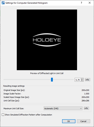
The CGH computation needs information about the resulting holographic image in far field. A dialog will open once to select the resulting image size compared to the unit cell size, and to select the maximum unit cell size used in computation. When multiple files were selected, the dialog will open only once and will apply the same settings from the first image file to all.
Possible image formats are BMP, PNG, JPEG, GIF, XBM, XPM, MNG and the different PNM formats: PBM (P1 or P4), PGM (P2 or P5), and PPM (P3 or P6). The CGH is computed by using an iterative Fourier Transformation Algorithm (IFTA). The algorithm converts the phase into gray levels from 0 to 255 assuming the SLM is properly calibrated to 2.0 π rad phase shift. The phase data result is a grayscale image.
With version 4.0 and later of the HOLOEYE SLM Pattern Generator Software, we introduce a new feature called CGH batch computation. The CGH batch computation should be used when many image files shall be used to generate hologram phase functions. It is especially designed to compute image sequences for later slideshow playback, e.g. using HOLOEYE SLM Slideshow Player software. Therefore, it can save the resulting phase fields directly into image files. Additionally, it provides easy testing by directly addressing the result onto the SLM screen.
Elementary Optical Functions
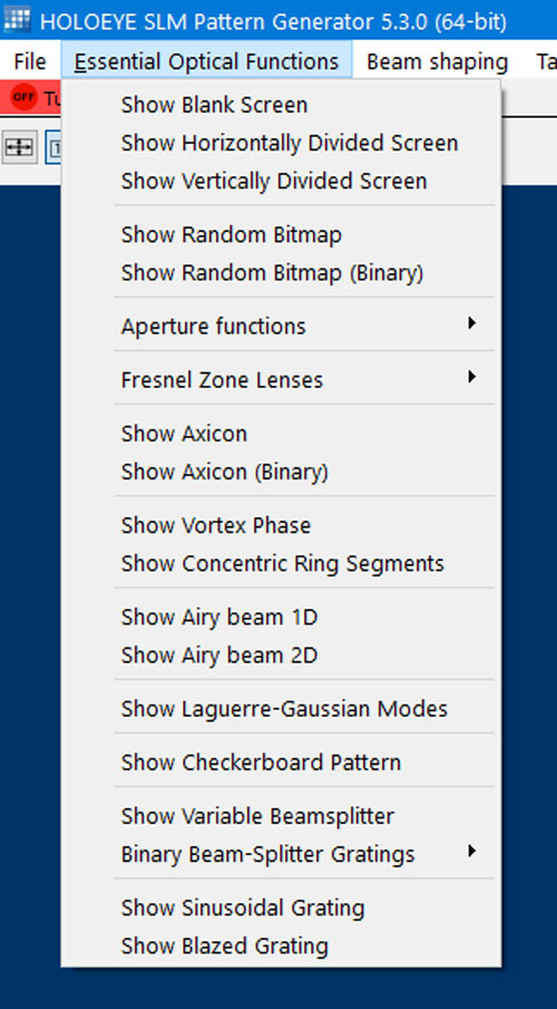
Besides the generation of CGHs a wide range of basic optical functions can be created directly via the menu bar. After input of the required parameters the output image appears in a new window. There are several binary and multilevel optical functions possible:
- Blank Grey Level Screen
With this function you can create a homogeneous gray level screen. - Horizontally Divided Screen
With this function you will create a horizontally divided screen, consisting of two homogeneous graylevel partial screens. - Vertically Divided Screen
With this function you will create a vertically divided screen, consisting of two homogeneous graylevel partial screens. - Random Bitmap
With this function you will create a random pixel distribution using 256 grayscale values. This function can be used to realize the optical function of a random phase plate. - Random Binary Bitmap
With this function you will create a random pixel distribution using only two grayscale values. This function can be used to realize the optical function of a random binary phase plate. - Aperture Functions
- Rectangular Aperture
- Circular Aperture
- Single Slit and Double Slit
- Fresnel Zone Lenses
- Binary Fresnel Zone Lens
- Multilevel Fresnel Zone Lens
- Cylindrical Fresnel Zone Lens
- Binary Axicon
With this function you will create a Binary Axicon graylevel image representation. - Axicon
With this function you will create a 256-level Axicon graylevel image representation. - Vortex Phase
Use this function to create a 256-graylevel image representation of a vortex phase. - Concentric ring segments
Use this function to create binary images consisting of concentric ring segments. - Airy Beam 1D
Use this function to create a 256-level grayscale image representation of a one-dimensional cubic phase function for the generation of a one-dimensional Gaussian-Airy beam. - Airy Beam 2D
Use this function to create a 256-level grayscale image representation of a two-dimensional cubic phase function for the generation of a two-dimensional Gaussian-Airy beam. - Laguerre-Gauss Modes
This function creates phase masks that generate Laguerre-Gaussian modes. - Checkerboard Pattern
This function generates checkerboard patterns with variable size. - Variable Beamsplitter
This function generates an array of M x N beams from the incident beam. - Binary beam-splitter gratings
- Linear Gratings and Crossed Linear gratings
- Exemplary built-in Binary Beam-Splitter Designs
- Sinusoidal Grating
With this function you will create a sinusoidal grating. - Blazed Grating
With this function you will create a blazed grating. - Calculating a beam-shaping phase function for Gaussian Input beams
- Transformation of a Gaussian beam to a circular ‘flat-top’ beam
- Transformation of a Gaussian beam to a rectangular ‘flat-top’ beam
Superposition of Phase Functions
Besides the generation of CGHs a wide range of basic optical functions can be created directly via the menu bar. After input of the required parameters the output image appears in a new window. There are several binary and multilevel optical functions possible:
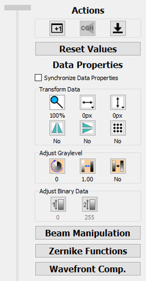
- Beam Manipulation Phase Overlay
The software allows superposition of a beam manipulation phase overlay to the image data of each tab. Three functions are available: Beam steering in both directions x and y (blazed gratings), and a Fresnel zone lens overlay. - Zernike Parameter Phase Overlay
Zernike parameters will create a smooth optical wave front added to the displayed phase data. The phase values are generated out of the Zernike polynomials with their corresponding Zernike parameters. Zernike polynomials and parameters are available up to the 4th order. Zernike parameters will be applied to all tabs synchronously. The feature was added to correct for optical setup imperfections, like correcting the flatness of an optical element or optimizing the beam profile. - Wavefront Compensation Phase Overlay
The Pattern Generator software allows to load a full screen phase overlay field, which electro optically compensates for physical deformation of the displays backplane. The deformation of the backplane typically leads to a deformation of the wavefront of the reflected light. This can be compensated by addressing the inverse deformation as a phase pattern on the SLM. It requires a measurement of the wavefront deformation introduced by the display. Wavefront compensation files are avaiable for LCoS SLM devices shipped after March 2021, containing an optical path difference field of the deformation.
To get access to the latest version of the SLM Pattern Generator software, please register at our download website.