Spatial Light Modulators
Spatial Light Modulators
 Spatial light modulator (SLM) is a general term describing devices that are used to modulate amplitude, phase, or polarization of light waves in space and time. HOLOEYE´s Spatial Light Modulator systems are based on translucent (LCD) or reflective (LCOS) liquid crystal microdisplays.
The use of LC materials in SLMs is based on their optical and electrical anisotropy. A certain gray level represents a defined average voltage across the LC cell. This voltage leads to a variable tilt of the LC molecules due to their electrical anisotropy. As LC molecules also show optical anisotropy this tilt changes the refractive index of the LC molecules (for suitable incident polarization, dependent on device version) which causes a modified optical path length within the LC cell. The addressed gray level is now converted into a phase level.
HOLOEYE’s SLMs are based on vertical aligned nematic (VAN), parallel aligned nematic (PAN) or twisted nematic (TN) microdisplay cells. In a twisted cell, the orientation of the molecules differs by typically 45°/90° between the top and the bottom of the LC cell and is arranged in a helix-like structure in between. In VAN/PAN cells the alignment layers are parallel to each other, so the LC molecules have the same orientation.
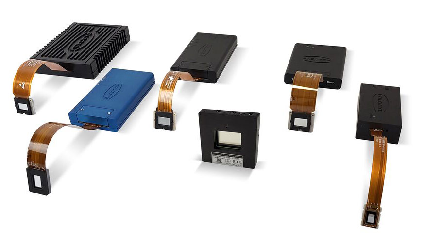
HOLOEYE Spatial Light Modulators
Find Product
Product
Reflectivity
Max. Phase Shift
Wavelength Range
Comment
Recommendation
Inquiry
Spatial Light Modulator Applications
- Holography (AR/VR/MR / Holographic Display, Digital- / Computer Holography, CGH)
- Quantum Optics / Optical Computing
- Deep Learning / Neural Networks
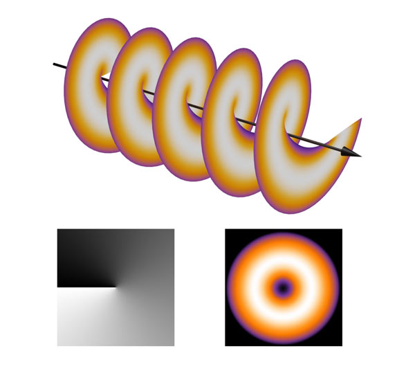
- Higher Order Modes / Optical Vortex / AOM
- WSS – Wavelengths Selective Switching
- Microscopy
- Bessel- /Airy Beams
- Material Processing
- Optical Trapping / Tweezers
- Laser Pulse Modulation
- Image Processing
- Interferometry
- Lithography
- Polarization Generation